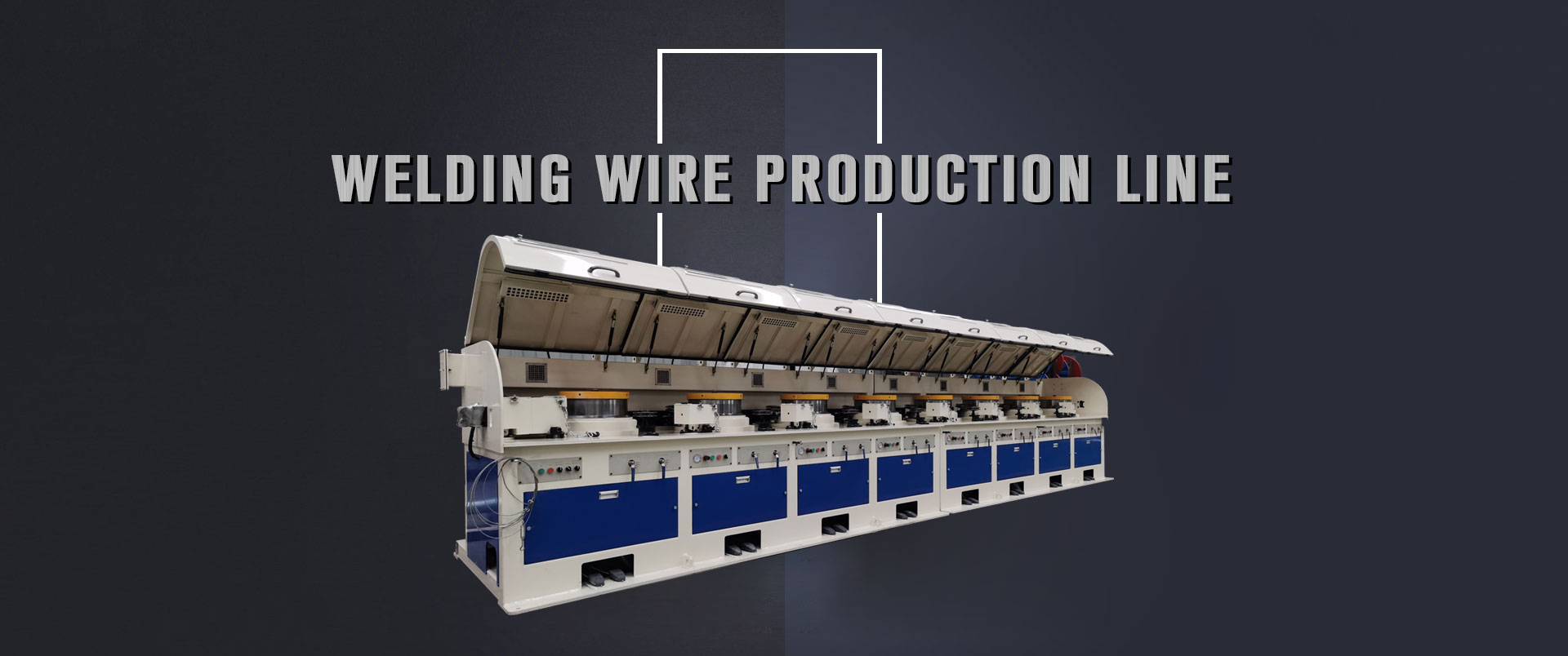
The use of frequency conversion speed regulation in the control of the straight wire drawing machine has the characteristics of concise configuration, clear logic and lower cost. At the same time, this article also introduces the application of Inovance MD320 frequency converter in the wire drawing machine in detail.
Key words: straight wire drawing machine, synchronization, frequency conversion control
1 Introduction
Metal products are an important part of the metallurgical industry, but this industry is a weak link in my country. Outdated machinery and electrical equipment hinder the development of the industry. In metal processing, the straight wire drawing machine is a common one. In the past, the DC generator-motor unit (FD system) was usually used to realize it. Now with the advancement of technology and the popularization of frequency converters, frequency conversion control Started to be widely used in the straight wire drawing machine, and can realize the functions of drawing variety setting, operation automation, production process control, real-time closed loop control, automatic meter counting and so on through PLC.
The straight wire drawing machine with variable frequency speed regulation system has advanced technology and significant energy saving. The speed regulation range is 30:1 during normal operation and can provide more than 1.5 times the rated torque at 5% of the rated speed.
This article takes the frequency conversion transformation of a straight wire drawing machine that produces stainless steel wire in a certain factory as an example to illustrate the application process and effect of frequency conversion control.
2 Frequency conversion control system of straight wire drawing machine
The straight wire drawing machine mainly draws the stainless steel wire that is finished rolling. The design process requirements are:
(1) The maximum wire drawing speed is 600m/min;
(2) There are three main types of processing, namely the incoming wire 2.8mm→ Outgoing wires 1.2mm, 2.5mm→1.0mm, 2.0mm→0.8mm;
(3) No more than 2 broken ends in emergency stop.
The straight wire drawing machine is one of the most difficult to control in the wire drawing machine. Because it is a wire drawing machine with multiple motors at the same time, the work efficiency is very high. Unlike the water tank wire drawing machine and loop wire drawing machine that are often encountered before, the wire is allowed to slip between the various molds. At the same time, it has higher requirements for the synchronization of the motor and the rapidity of dynamic response. Due to the brittle nature of stainless steel materials, it lacks the toughness like high-carbon steel wires or steel cords, and it is easier to break during operation.
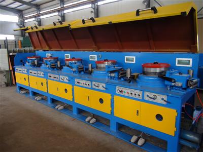
There are 8 11KW inverters in this system. The electrical configuration of the system is a looper, which is installed in the first stage. The function is to draw the coiled stainless steel wire to the drawing part. Because the looper can freely slip, this motor does not require special control. There are six drums with a diameter of 400mm in the drawing part. A cylinder swing arm for detecting the position is installed between each drum. The position of the swing arm can be detected by a displacement sensor. When the wire is tightened, the wire will generate pressure on the cylinder of the swing arm to move the swing arm down. . The final is the winding motor. This part adopts a self-sliding conical bracket. The winding diameter is basically unchanged during the whole process, so the winding diameter calculation function is not needed. The power of the eight motors adopts frequency conversion dedicated motors, and they are equipped with mechanical braking devices.
The system logic control of the straight wire drawing machine is more complicated, there are various linkage relations, and it is realized by PLC. The synchronization control is all implemented inside the Inovance MD320 inverter, and does not rely on external control.
Its working principle is: according to the operator's setting on the panel to determine the operating speed, the analog signal of this speed enters the PLC, and the PLC outputs the analog signal at a certain slope after considering the acceleration and deceleration time. The purpose of this is mainly to meet the needs of some operations such as inching and threading. The analog voltage signal output by the PLC is connected to the AI2 (AI1 can also) input terminals of all inverters at the same time as the main speed reference signal. The signal of each swing arm displacement sensor is connected to the corresponding drum drive frequency converter as the feedback signal of PID control. According to the position of the swing arm in the middle, set a given value of PID by yourself. This system is a very typical PID control system with feedforward, one stage in series with one stage, and PID as the fine-tuning quantity.